This article will talk about the Assembly Language Programming 8085 Microprocessor. Intel created the 8085 microprocessor, an 8-bit processor, in the mid-1970s. In the early days of personal computing, amateurs and enthusiasts frequently chose it because of its simplicity and ease of use.
Also learn: Assembly Language Programming 8086
Assembly Language Programming 8085 Microprocessor
In the Assembly language programming 8085, the 8085 microprocessor’s assembly programming language involves writing low-level scripts that control the hardware directly. This form of programming is vital for grasping how microprocessors function, enhancing performance, and executing important real-time applications. The 8085 microprocessor, featuring a straightforward architecture and instruction set, serves as a great foundation for understanding assembly language programming.
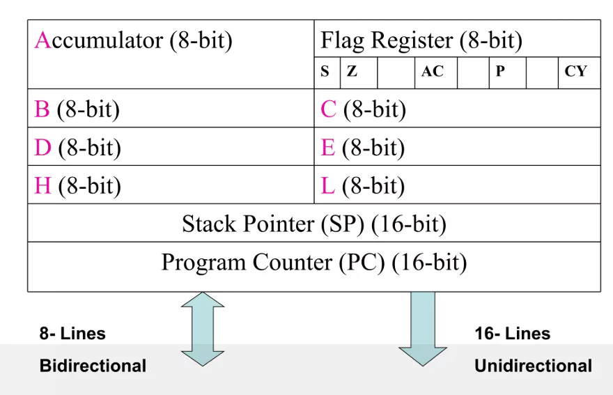
Programming Model of 8085
- A microprocessor cannot comprehend an assembly language program.
- A program called Assembler is used to translate programs written in Assembly language into machine language.
Understanding the above model.
Let’s examine the 8085 microprocessor’s programming in the Assembly language programming 8085.
In the Assembly language programming 8085, Instruction sets are sets of codes used to carry out specific tasks. It is divided into five groups.
- Instructions for Control: The table that follows lists the control instructions along with their definitions.
- Reasonable Directions: The table that follows lists logical instructions along with their definitions.
- Instructions for Branching: The table that follows lists the branching instructions along with their definitions.
- Instructions in Arithmetic: The table that follows lists arithmetic instructions along with their definitions.
- Instructions for Data Transfer: The table that follows lists data-transfer commands along with their definitions.
Demo Programs for 8085
In the Assembly language programming 8085. Using the instructions above, let’s now examine some program demonstrations.
Problem 1: Create an assembly language program that adds two 8-bit values that are kept in the 8085 microprocessor at addresses 2050 and 2051. The program’s start address is assumed to be 2000.
The algorithm
- Put the initial integer into the accumulator from memory location 2050.
- Transfer the accumulator’s contents to register H.
- It is necessary to load the second number from memory location 2051 into the accumulator.
- The contents of register H and the accumulator are then added using the “ADD” instruction, and the result is stored at 3050.
- The generated carry is retrieved using the “ADC” command and then stored at memory location 3051.
Program
| Memory Address | Mnemonics | Comment |
|---|---|---|
| 2000 | LDA 2050 | A ← [2050] |
| 2003 | MOV H, A | H ← A |
| 2004 | LDA 2051 | A ← [2051] |
| 2007 | ADD H | A ← A + H |
| 2008 | MOV L, A | L ← A |
| 2009 | MVI A 00 | A ← 00 |
| 200B | ADC A | A ← A + A + carry |
| 200C | MOV H, A | H ← A |
| 200D | SHLD 3050 | H → 3051, L → 3050 |
| 2010 | HLT |
Explanation of the Above Program
- LDA 2050 explains that it transfers the data from the 2050 memory location to the accumulator. (Opcode: 3A 50 20)
- MOV H, A duplicates the contents of the Accumulator in order to register H to A. (Opcode: 67)
- LDA 2051 transfers the contents of the 2051 memory location to the accumulator. (Opcode: 3A 51 20)
- The contents of the H register (F9) and A (Accumulator) are added by using ADD H. The outcome is kept in A itself. All arithmetic instructions by default use A as an operand, and the result is saved as well (Opcode: 84).
- The contents of A (34) are copied to L via MOV L, A (Opcode: 6F).
- MVI Data (i.e., 00) is moved immediately to A by A 00 (Opcode: 3E 00).
- The contents of the given register (A), the contents of A(00), and carry (1) are added by ADC A. A is by default an operand and saves the result because ADC is also an arithmetic operation (Opcode: 8F).
- MOV H, A transfers A (01)’s contents to H (Opcode: 67).
- SHLD 3050 is used to move the contents of the L register (34) to the 3050 memory location and the contents of the H register (01) to the 3051 memory address (Opcode: 22 50 30).
- HLT ends the program’s execution and prevents it from continuing (Opcode: 76).
Functional Units of 8085 Microprocessors
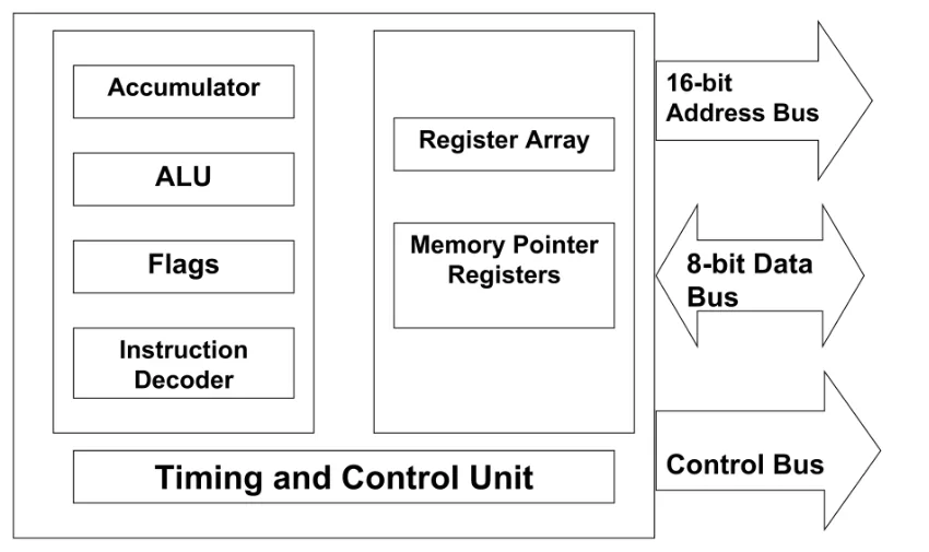
The following functional units make up 8085 in the Assembly language programming 8085 are:
The Accumulator
Arithmetic, logical, I/O, and LOAD/STORE operations are all carried out by this 8-bit register. It is linked to the ALU and internal data bus.
Arithmetic Unit and Logic Unit
As the name implies, it works with 8-bit data to carry out arithmetic and logical operations such as addition, subtraction, AND, OR, etc.
General purposes Register
The 8085 CPU has six general-purpose registers: B, C, D, E, H, and L. 8-bit data can be stored in each register.
These registers have the ability to store 16-bit data in pairs, and their pairing combinations are similar to B-C, D-E, and H-L.
Counter for the program
The memory address location of the subsequent instruction to be executed is stored in this 16-bit register. The microprocessor advances the program each time an instruction is executed, pointing the program counter to the memory address of the next instruction that has to be executed.
Stack pointer
Additionally, it is a 16-bit register that functions similarly to a stack and is always increased or decreased by two when push and pop operations are performed.
Temporary register
In the Assembly language programming 8085, the temporary data for arithmetic and logical operations is stored in this 8-bit register.
Flag Register
Depending on the value stored in the accumulator, the 8-bit register’s five 1-bit flip-flops can contain either 0 or 1.
These are the five flip-flops in the collection.
- Sign (S)
- Zero (Z)
- Auxiliary Carry (AC)
- Parity (P)
- Carry (C)
Decoder and instruction register
In the Assembly language programming 8085, the 8085 register has eight bits. An instruction is saved in the instruction register once it has been fetched from memory. An instruction decoder decodes the information stored in the instruction register.
Control of interruptions
In the Assembly language programming 8085, As the name suggests, it controls disruptions during a process. Every time an interrupt occurs while a microprocessor is running a main program, it switches control from the main program to handle the incoming request. When the request is complete, the control goes back to the main program.
The 8085 microprocessor has five interrupt signals: TRAP, RST 5.5, RST 7.5, RST 6.5, and INTR.
Control of serial input/output
These two instructions—SID (Serial input data) and SOD (Serial output data)—are used to regulate serial data communication.
Data bus and address bus
The data is transported to storage via a data bus. It is bidirectional, while the address bus is unidirectional and transports the location to the storage location. It is employed to address I/O devices and transfer data.
The address-data buffer and the address buffer
To connect with the CPU, the information kept in the program counter and stack pointer is loaded into the address buffer and address-data buffer. These buses connect the memory and I/O chips, allowing the CPU to exchange the needed data with them.
Conclusion on the Assembly Language Programming 8085 Microprocessor
This chapter has detailed talked about the Assembly language programming 8085 Microprocessor and its instruction set covering all the features and therefore we may infer from the description above that the 8085 microprocessor is a great option for many applications due to its many characteristics.


